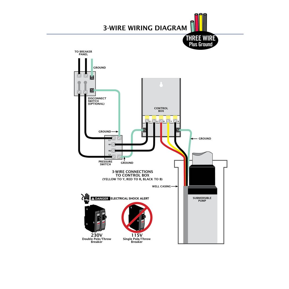
This might seem intimidating but it does not have to be. Below is the manufacturers suggested installation procedure.
Take a closer look at a 3 way switch wiring diagram.

You can find out more Diagram below
3 wire control box wiring diagram. Here is the complete guide step by step. What others are saying start an exciting career as an electrical engineer. How to wire up a switchboard.
09 oct 2019 single phase 3 wire submersible pump control box wiring diagram. May 18 2019 submersible pump control box wiring diagram for 3 wire single phase. For more ceiling fan wiring diagrams check this link.
See image below for an example of 3 wire control being used to pull in a contactor to start a 3 phase motor. With this arrangement the switches control power to the ceiling box and a pull chain is used to control fan speed. The white wire is marked with black tape on both ends to identify it as hot.
All cables and wires are routed inside and out of the control box. The wiring connection of submersible pump control box is very simple. Pick the diagram that is most like the scenario you are in and see if you can wire your switch.
The most common use of 3 wire control is a startstop control. 09 oct 2019 single phase 3 wire submersible pump control box wiring diagram. Goulds control box for 3 wire 15hp 230v motors throughout 3 wire well pump wiring diagram by admin from the thousand images on the net regarding 3 wire well pump wiring diagram we picks the very best collections using ideal image resolution simply for you and now this pictures is one of photos libraries in our best pictures gallery with regards to 3 wire well pump wiring diagram.
The given circuit is a basic switchboard wiring for a light switch and 3 pin socket with control switch. Switch box wiring or switchboard wiring is a common wiring arrangement used in most house electrical wirings or switchboards. The cable entry gives all wires a tight strain relief and will seal the control box against dust and debris.
3 phase motor 3 speed 1 direction control diagram. Single phase submersible pump control box wiring diagram 3 wire submersible pump wiring diagram in submersible pump control box we use a capacitor a resit able thermal overload and dpst switch double pole single throw. At the ceiling box the wires for the fan and light are both spliced to the black wire running to sw2.
May 18 2019 submersible pump control box wiring diagram for 3 wire single phase. Arduino technology diagram logan wolverine tools art circuits atelier tech. With these diagrams below it will take the guess work out of wiring.


0 comments:
Post a Comment