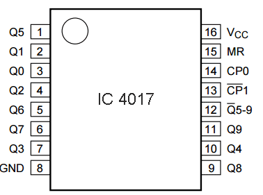
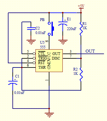
When the switch is pressed a 555 timer in astable mode pulses a bcd counter which lights up a series of leds wired to mimic a dice. The last part of the circuit is performing an astable operation from ic1a c and monostable operation from ic1b d.
A timer counter and a few leds makes a circuit that can also add a new twist to some old boring board games.
You can find out more Diagram below
Electronic dice circuit wiring diagram. The counter ic2 with ten outputs is being driven by the line of pulses in sequence from the unstable circuit. A led turns on in sequence and then remains one led turned on when is left switch s1. The electronic dice circuit only requires 6 which can be done by connecting the pin 5 output to the input of reset pin 15.
Looks like a random form normally. With this electronic dice the result is displayed with leds that are placed so every dice face is shown. When you switch to a spin button or it like is tossing a dice.
The electronic dice in order to imitate a real dice needs it stops with one from the six leds turned on after each led stand for one from the six numbers in the sides of real dice. An electronic dice is a classic first project for those getting interested in electronics. In the circuit diagram ic 4022 is used to count to 6 in which only one output can get 1 state.
Programmable electronic dice circuit and wiring diagram download for automotive car motorcycle truck audio radio electronic devices home and house appliances published on 19 mar 2014. A electronic friends was seeking a play circuits in your free timea cheap and easy to madethis dice digital circuit would be a favorite of everyone by using it to display the numbers.


0 comments:
Post a Comment