Two for power 5v gnd and two for differential data signals labelled as d and d in pinout. There are a couple of standards and there is also crossover cable so make sure you study the rj45 pinout diagrams below to get the right one for your needs.
Make sure you use the correct rj45 pinout wiring diagram for your needs.

You can find out more Diagram below
Usb coaxial wiring diagram. Usb pinout signals usb is a serial bus. A wiring diagram is a simplified traditional photographic representation of an electric circuit. Orange white blue and green usb wires inside this usb cable usb have problems like loose connections and the like.
So keep coax cables as least 6 in. It uses 4 shielded wires. If the coax must cross over an electrical line create a 90 degree intersection.
We can peel off or do the skinning of your usb wires to know what is inside. It shows the parts of the circuit as streamlined shapes and the power and also signal connections in between the tools. Half duplex differential signalling is used to reduce the effects.
Usb wire cable and the different wire colors. The usb standard supports the data transfer at the rate of 12 mbps. In usb data cable data and data.
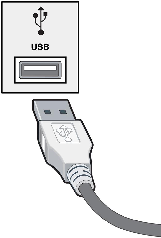
Usb is the short form of universal serial bus a standard port that helps to connect computer peripherals like scanner printer digital camera flash drive and more to the computer. The cable can be used to transfer data from 1 apparatus to another. Most of them use usb cable.
Usb is a serial bus. In a usb data cable data and data signals are transmitted on a twisted pair with no termination needed. To reduce any chance of trouble from phone lines install twisted pair or shielded phone wiring.
Away from electrical cable even if the cables are separated by wood or other building materials. Assortment of usb to rca cable wiring diagram. The following is for t568 b most common.
Usb splitter wiring diagram powered usb hub wiring diagram usb hub circuit diagram usb splitter wiring diagram there are lots of types of electronic gadgets on the market. A wiring diagram is a simplified conventional pictorial representation of an electric circuit. Two for power 5v gnd and two for differential data signals labelled as d and d in pinout.
Nrzi non return to zero invert encoding scheme used to send data with a sync field to synchronise the host and receiver clocks. It shows the components of the circuit as simplified forms as well as the power and also signal connections between the devices. Assortment of usb to rj45 cable wiring diagram.
Orange white blue and green learn what each colored wire inside a usb cord means. It uses 4 shielded wires. It can also link device to a power supply for charging function.


_small.png)

0 comments:
Post a Comment